MeshZero HAT
A 1W Meshtastic HAT for the Raspberry Pi Zero with an integrated 12V buck converter, SMA output, and SX1262 LoRa module.
• Matthew Lyon
Status: Shipping in progress
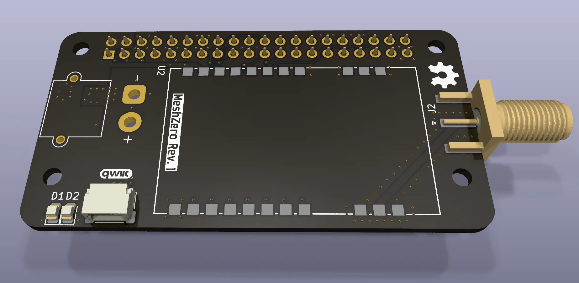
MeshZero is a compact Meshtastic-compatible LoRa HAT designed to fit the Raspberry Pi Zero. The board uses the Ebyte E22-900M30S LoRa module, which is based on the Semtech SX1262 and packaged in a large castellated form factor suitable for high-power operation.
The goal of the project was to create a small, self-contained Meshtastic node capable of operating from a 12 V supply while supporting high RF output power and an external antenna.
Overview
This project was a design my dad and I came up with to meet our needs for a 12 V Meshtastic node with higher output power than typical off-the-shelf boards. The primary challenge was fitting the radio, power conversion, and Raspberry Pi HAT interface into a very constrained form factor without compromising RF performance or power integrity.
Early in the design process, I attempted to use a discrete buck controller that required an external inductor. After spending several hours attempting to produce a layout I was happy with, it became clear that the footprint, routing constraints, and current handling requirements made this approach impractical for a board of this size.
A few days later, I discovered the Monolithic Power Systems MPM line of integrated power modules. The MPM3620A proved to be a good fit for this design, providing a compact solution capable of delivering 5 V at up to 2 A without the need for an external inductor.
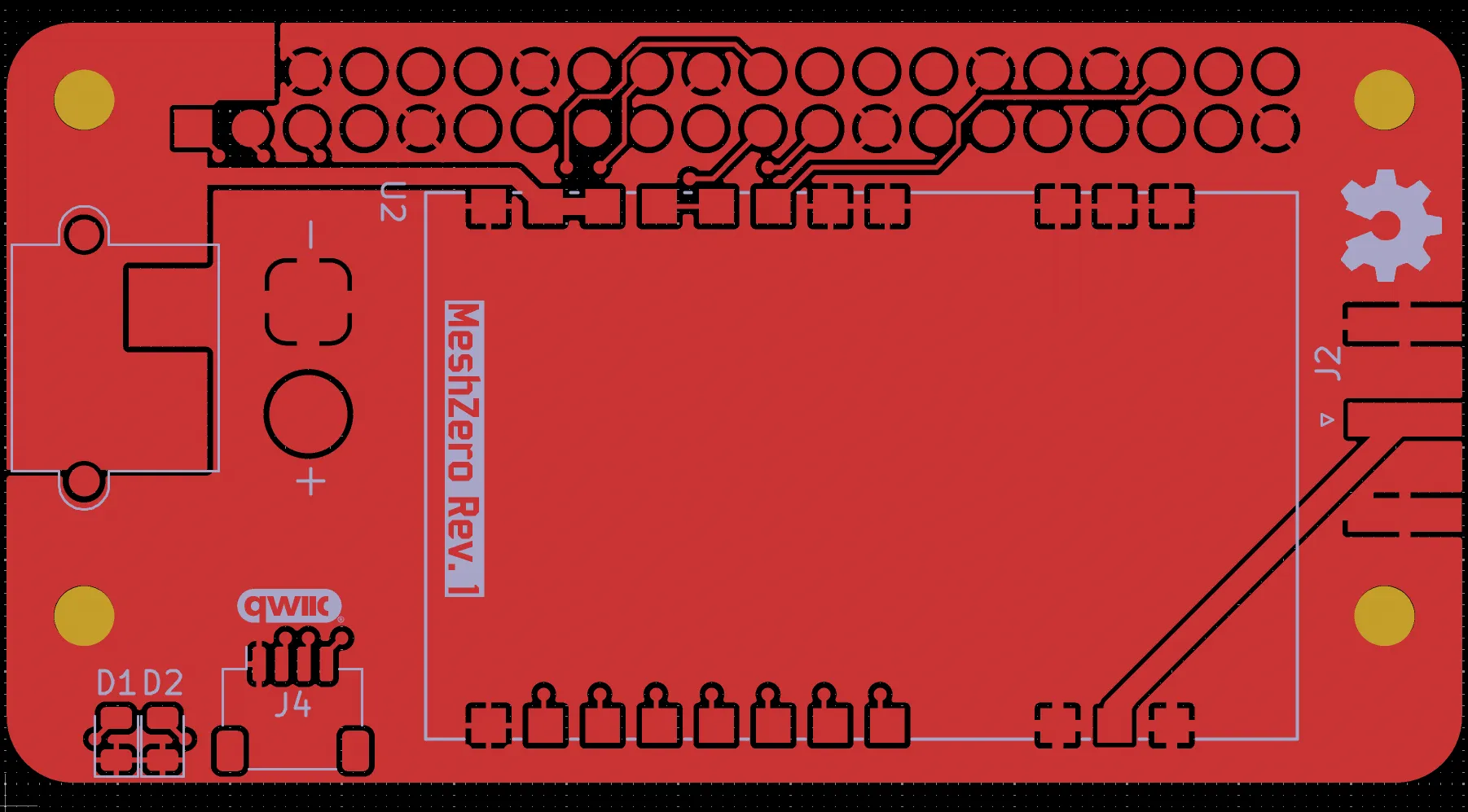
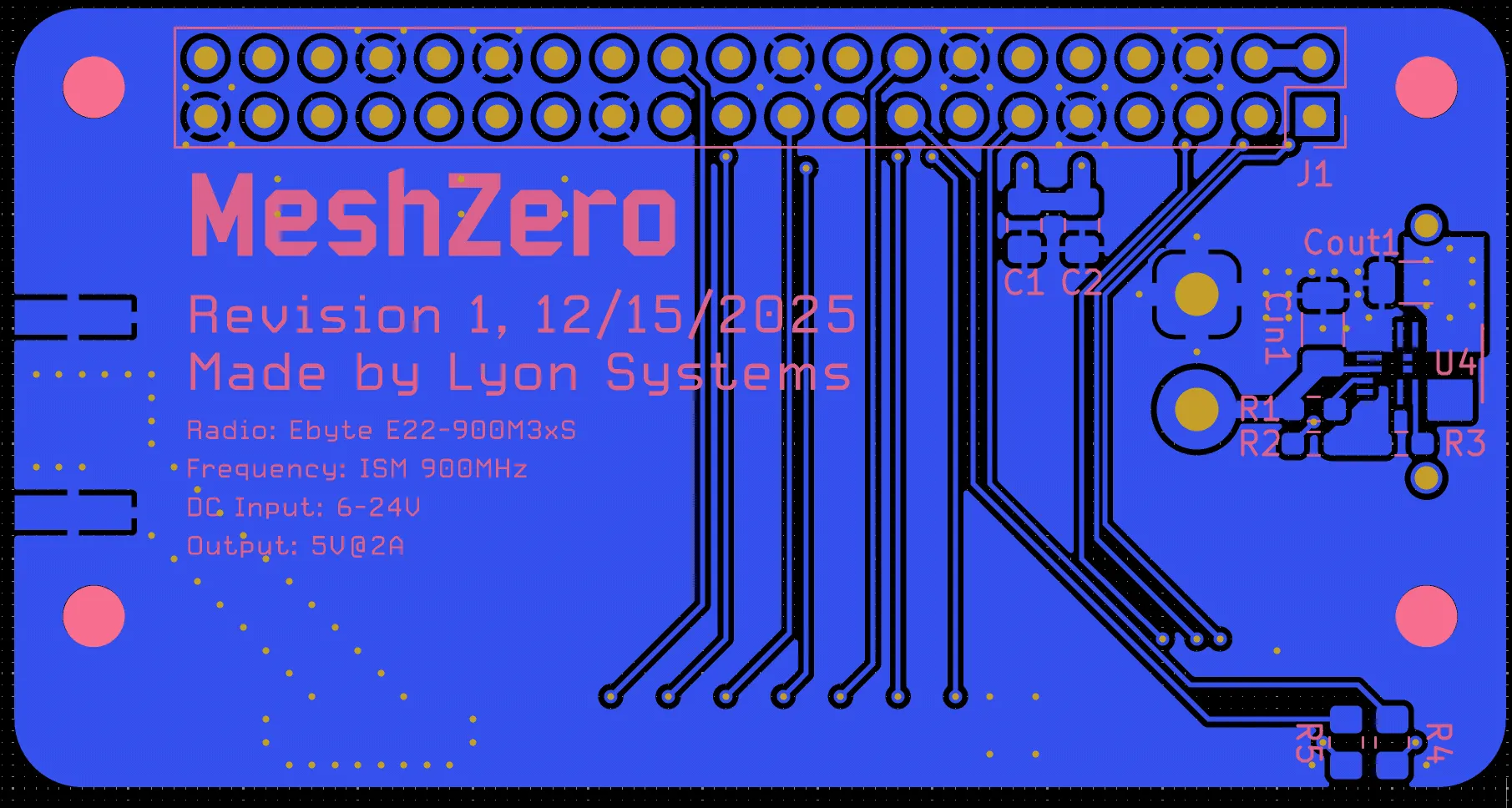
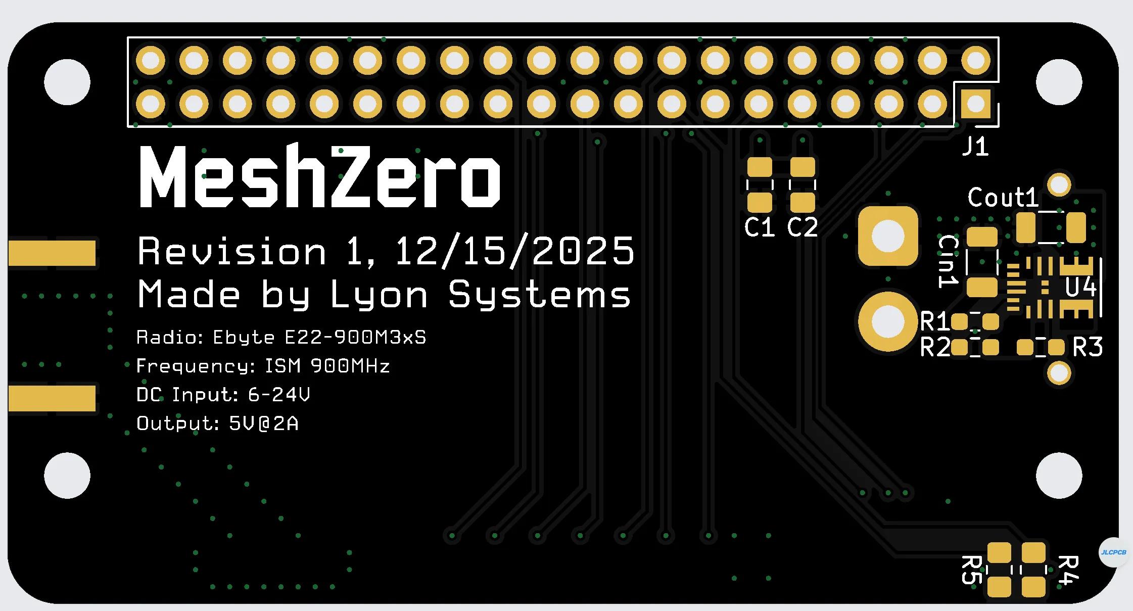
Gerber views of the top and bottom copper layers.
Note the Open Source Hardware logo - I will be making this board’s files public once I confirm its functionality.
Power Architecture
The MPM3620A buck converter is placed beneath the XT-30 power connector to make efficient use of the available board area. This placement required careful attention to routing and copper pours, but allowed the overall board footprint to remain compact.
One unexpected complication was the XT-30 connector itself. The naming convention for the connector is somewhat counterintuitive: the housing that appears “male” is electrically female due to the internal pin structure. This required extra care during schematic capture and footprint selection to ensure correct polarity.
The board is designed to accept a 6-24 V input and regulate it down to 5 V for both the Raspberry Pi and the LoRa module.
RF Layout and Transmission Line Design
Routing the RF output from the E22-900M30S module to an edge-mount SMA connector required careful impedance control. Because this is a two-layer PCB with approximately 1.6 mm between the top and bottom ground planes, I used a coplanar waveguide with ground (CPWG) transmission line.
The RF trace is surrounded by stitching vias to maintain a consistent return path and reduce impedance discontinuities. This approach was chosen to achieve a reasonable 50 Ω match given the stackup constraints and limited layer count.
Assembly
The board has not yet been assembled at the time of writing. A solder stencil was ordered to assist with assembly, particularly for the MPM3620A, which has a relatively complex footprint. Assembly is planned to be done in the Hive makerspace at Georgia Tech.
Known Design Tradeoffs and Considerations
There are several design considerations that were identified during development and could not be fully mitigated.
Reverse Current into Raspberry Pi USB
Based on forum discussions and documentation, the Raspberry Pi does not include reverse-current protection on its USB power inputs. If the HAT is powered while a USB device or host is connected, and the voltage is out of range, there is a possibility of reverse current flowing back into the USB interface.
Because this behavior is internal to the Raspberry Pi and cannot be addressed on the HAT itself, this was considered an unavoidable limitation of the design.
Routing Under the LoRa Module
The E22-900M30S documentation recommends avoiding routing under the bottom of the module to prevent high-frequency coupling. Due to the spacing and location of the Raspberry Pi GPIO pins, SPI and control signals had to cross beneath the module.
To mitigate this, all such routing was placed on the bottom layer to increase separation from the radio module. Based on the routing geometry and signal characteristics, this is expected to be acceptable in practice.
Power Supply Ripple
The E22-900M30S recommends powering the radio through an LDO to further isolate it from switching noise. In this design, the radio is powered directly from the buck converter output without additional linear regulation.
Local decoupling capacitors (0.1 µF and 1 µF) are placed at the radio’s power input to attenuate high-frequency ripple from the MPM3620A’s ~2 MHz switching frequency. This was deemed sufficient for an initial revision of the board.
Outlook
While there are known tradeoffs, the design choices were made deliberately based on size, complexity, and intended use. I am confident the board will function as intended once assembled and tested, and it will serve as a solid platform for further experimentation with high-power Meshtastic nodes.
Additional Photos
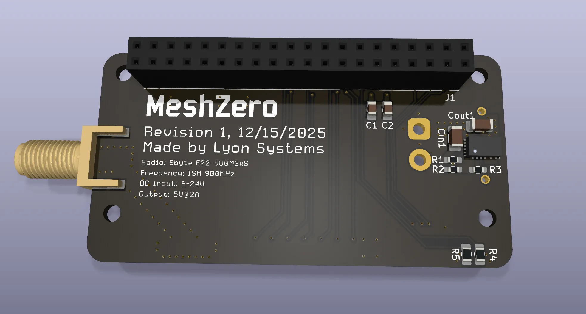
Kicad’s 3D render of the back of the board when fully assembled.
The bottom side of the board as rendered by JLCPCB.